Web based School


- 11 — Drawing and Device Contexts
11 — Drawing and Device Contexts
11 — Drawing and Device Contexts
To say that drawing on the screen, the printer, or another output device is one of the most important aspects of a Windows application is stating the obvious. Throughout their lifetimes, Windows applications continually draw and redraw the contents of their windows in response to user actions or other events.
Needless to say, applications draw to hardware devices using a series of device-independent system functions. Otherwise Windows applications, similar to their MS-DOS counterparts, would be plagued with device incompatibilities and would require device drivers for various video cards, printers, or other graphics hardware. Indeed, device independence is one of the major advantages of offered by a graphical operating system like Windows.
The GDI, Device Drivers, and Output Devices
Applications wishing to draw to an output device do so by calling Graphics Device Interface, or GDI functions. The GDI library containing these functions, gdi.dll, makes calls, in turn, to device-specific function libraries, or device drivers. The device drivers perform operations on the actual physical hardware. Device drivers are supplied either as part of Windows or, for less commonly used hardware, as third-party add-ons . The interrelationship between graphical applications, the GDI, device driver software, and hardware devices is schematically illustrated in Figure 11.1.
Figure 11.1. Interaction between applications, the GDI, device drivers, and output devices.
Most drawing functions take a handle to a device context as one of their parameters. In addition to identifying the device on which the drawing should take place, the device context also specifies a number of other characteristics, including
- Mapping of logical coordinates to actual physical coordinates on the device
- Use of drawing objects such as fonts, pens, or brushes to carry out the requested operation
- Clipping of drawing functions to visible areas
Device Contexts
A device context thoroughly specifies the characteristics of a hardware device. Drawing system functions use this information to translate device-independent drawing calls into a series of device-specific operations carried out with the help of low-level driver code.
Before a device context can be used, it must be created. The most generic function for creating a device context is the CreateDC function. When calling this function, applications specify the device for which the device context is created, the driver software, the physical port to which the device is attached, and device-specific initialization data.
When drawing to the screen, applications need not create a device context using CreateDC. Instead, applications can retrieve a handle to a device context representing the client area of a window through the GetDC function or the entire window (including nonclient areas) through GetWindowDC.
A typical GDI drawing function is the Rectangle function. An application may make the following call to draw a rectangle:
Rectangle(hDC, 0, 0, 200, 100);
This call draws a rectangle on the device identified by the handle hDC, with its upper-left corner at logical coordinates [0,0], and lower-right corner at [200,100]. Needless to say, a lot takes place behind the scenes before the actual rectangle is formed on the screen. How does the GDI know the physical coordinates corresponding to these logical coordinates? How does it know the color of the rectangle and its interior? The styles used for the rectangle's contours or for filling its interior? The answer is, all this information is available as part of the device context. Coordinate transformations are defined by the mapping mode and any world transformation that may be in effect. The appearance and color of objects drawn are a function of GDI objects which have been selected into the device context. All of this we review shortly.
Device Context Types
In the case of the display, Windows distinguishes between common and private device contexts. Common device contexts represent a shared resource across applications. Private device contexts are created for windows with a window class carrying the CS_OWNDC style. Private device contexts are deleted when the window to which they belong is destroyed.
Memory and Metafile Device Contexts
Device contexts typically represent physical devices, such as the display, the printer, plotters, or FAX modems. However, there are also some special device contexts in Windows. One of them I already mentioned. A memory device context is a device context that represents a bitmap. By utilizing this device context, applications can write into a bitmap.
In addition to the obvious use in creating bitmaps (such as in a bitmap editor like the Windows 95 Paint application), memory device contexts have another practical use in graphics-intensive applications. By drawing into a memory device context and transferring the contents only when the drawing is complete, applications can reduce unwanted screen flicker. Through a clever use of multiple memory device contexts, applications can create smooth animation effects. Several functions, which we review shortly, assist in efficiently transferring bitmap data from one device context to another.
A memory device context is created by a call to the CreateCompatibleDC function. This function creates a memory device context that is compatible with a specified physical device.
Another type of a device context is a metafile device context. A metafile is essentially a device-independent record of GDI operations. Win32 recognizes two metafile types: standard and enhanced metafiles. Standard metafiles are compatible with Windows 3.1, but they do not implement complete device independence; for this reason, the use of enhanced metafiles for new applications is recommended.
A metafile device context is created by calling the CreateMetaFile function or, in the case of enhanced metafiles, the CreateEnhMetaFile function. When an application is finished drawing into the metafile device context, it closes the metafile using CloseMetaFile (CloseEnhMetaFile). This call returns a metafile handle that can then be used in calls to PlayMetaFile (PlayEnhMetaFile) or the various metafile manipulation functions. A metafile handle can also be obtained by a call to GetMetaFile (GetEnhMetaFile) for metafiles that have been saved to disk previously.
Relatively few applications manipulate metafiles directly. However, most applications use metafiles implicitly through OLE. The device-independent metafile format is used by OLE to graphically represent embedded or linked objects. Applications that display embedded objects thus do not need to call the OLE server application (which may not even be installed on the system) every time an OLE object needs to be rendered; instead, they just play back the recorded metafile.
Information Contexts
Information contexts are used to retrieve information about a specific device. An information context is created by a call to the CreateIC function. Creating an information context requires far less overhead than creating a device context and is therefore the preferred method for retrieving information about a device. An information context must be deleted after use by calling DeleteDC.
Coordinates
Applications typically specify the position and size of output objects in the form of logical coordinates. Before an object appears at a physical location on the screen or printer, a series of calculations takes place to obtain actual physical positions on the device.
Logical and Device Coordinates
The transformation from logical to physical coordinates, although simple in concept, can sometimes trick even the experienced Windows programmer.
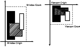
The mapping from logical to physical coordinates is accomplished by specifying the characteristics of the window and the viewport. The window, in this context, represents the logical coordinate space; the viewport represents the physical coordinate space of the device.
For both the window and the viewport, two pairs of values must be supplied. One pair is the horizontal and vertical coordinates of the origin; the other pair is the horizontal and vertical extent.
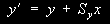
Figure 11.2 illustrates how the logical coordinates of a set of rectangles are mapped to device-specific physical coordinates. From this illustration, it should be clear that the absolute size of the logical and physical extents should be of no consequence; what matters is their relative sizes—that is, the number of logical units mapped to a physical unit or vice versa.
Figure 11.2. The logical and the physical coordinate system.
On most devices, the origin of the physical coordinate system is in the upper-left corner and the vertical coordinate grows downward. In contrast, in most logical coordinate systems, the origin is in the lower-left corner and the vertical coordinate grows upward.
The origin and the extent of the logical and physical coordinate systems can be set using the following four functions: SetViewportExtEx, SetViewportOrgEx, SetWindowExtEx, SetWindowOrgEx. (Use of the old functions SetViewportExt, SetViewportOrg, SetWindowExt, and SetWindowOrg is not supported in Win32.)
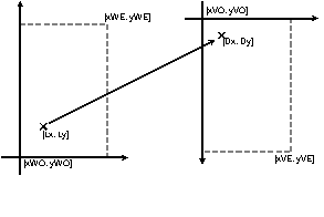
For reference, here is how the GDI converts from logical to physical coordinates and vice versa:
Dx = (Lx Ð xWO) * xVE/xWE + xVO

Dy = (Ly Ð yWO) * yVE/yWE + yVO

Lx = (Dx Ð xVO) * xWE/xVE + xWO

Ly = (Dy Ð yVO) * yWE/yVE + yWO
The meaning of these symbols should be fairly obvious; for example, Dx is the horizontal device coordinate, yWE is the vertical window extent. Figure 11.3 identifies these symbols graphically.
Figure 11.3. Mapping logical to physical coordinates.
To facilitate easy changes from one mapping to another, Windows offers a few helper functions. These include: OffsetViewportOrg, OffsetWindowOrg, ScaleViewportExt, and ScaleWindowExt.
Note that an application can change the horizontal or vertical orientation of the window or viewport by specifying a negative extent value.
To calculate explicitly a set of physical coordinates from logical coordinates, or vice versa, applications can use the LPtoDP and DPtoLP functions.
Constrained Mapping Modes
What has been said about mapping modes so far is true for the so-called unconstrained mapping mode.
The GDI supports several mapping modes; the unconstrained mapping mode MM_ANISOTROPIC is but one. Other mapping modes include the following:
MM_TEXT. The origin of the logical coordinate system is the upper-left corner, and vertical coordinates are growing downwards. In other words, MM_TEXT is the equivalent of no mapping at all. A logical unit equals one pixel.
MM_LOENGLISH. The origin is in the lower-left corner, and vertical coordinates grow upwards. A logical unit is equal to one hundredth of an inch (0.01").
MM_HIENGLISH. The origin is in the lower-left corner, and vertical coordinates grow upwards. A logical unit is equal to one thousandth of an inch (0.001").
MM_LOMETRIC. The origin is in the lower-left corner, and vertical coordinates grow upwards. A logical unit is equal to one tenth of a millimeter (0.1 mm).
MM_HIMETRIC. The origin is in the lower-left corner, and vertical coordinates grow upwards. A logical unit is equal to one hundredth of a millimeter (0.01 mm).
MM_TWIPS. The origin is in the lower-left corner, and vertical coordinates grow upwards. A logical one twentieth of a point (1/1440").
MM_ISOTROPIC. The only restriction is that horizontal and vertical logical units are of equal length. Applications can freely specify the origin of the logical and physical coordinate systems, as well the their horizontal extents. The vertical extents are computed from the horizontal by the GDI.
In the six constrained mapping modes, applications are free to change the viewport and window origin, but attempts to change the viewport or window extent (through SetViewportExtEx or SetWindowExtEx) are ignored.
World Coordinate Transforms
Flexible as the coordinate mapping capabilities in Windows are, Windows NT further extends these capabilities with the concept of World Coordinate Transforms. This capability makes it possible for applications to specify an arbitrary linear transformation as the mapping from the logical to the physical coordinate space.
To understand how world transformations work, it is necessary to delve into coordinate geometry.
Linear transformations fall into the following categories: translation, scaling, rotation, shear, and reflection.
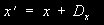
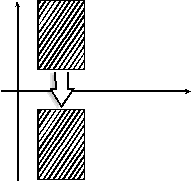
Translation (Figure 11.4) means that constants are added to both the horizontal and vertical coordinates of an object:
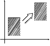
Scaling (Figure 11.5) means stretching or compressing the horizontal or vertical extent of an object:
During a rotation (Figure 11.6), points of an object are rotated around the origin. If the angle of the rotation, a, is known, the rotation can be expressed as follows:
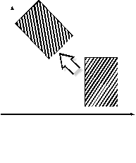
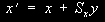
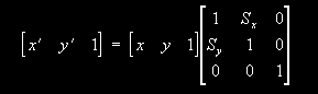
Shearing (Figure 11.7) is a transformation that turns rectangles into parallelograms. Shearing adds a displacement to point's horizontal coordinate that is proportional to the vertical coordinate, and vice versa. Shearing can be expressed by the following formulae:
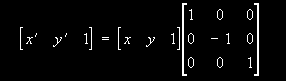
A reflection mirrors an object with respect to either the horizontal or the vertical axis. Figure 11.8 shows a reflection with respect to the horizontal axis. This reflection can be expressed with the following formula:
Figure 11.8. Reflection with respect to the horizontal axis.
A reflection with respect to the vertical axis can in turn be expressed as follows:
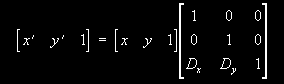
All these transformations can also be expressed in matrix form using 3x3 matrices. The matrix form of a translation is this:
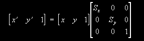
The matrix form of scaling:
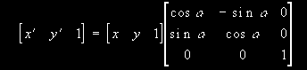
The matrix form of a rotation, expressed using trigonometric functions of the rotation angle:
The matrix form of a shearing:
A reflection with respect to the horizontal axis is expressed in matrix form as follows:
Finally, a reflection with respect to the vertical axis takes the following matrix form:
Linear transformations can be combined. The result of two linear transformations is a third linear transformation. In matrix formulation, the resulting transformation can be expressed as the product of the matrices representing the original transformation.
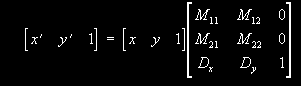
While any linear transformation can be expressed in the form of a series of the five basic transformations mentioned here, a generic linear transformation may not be a simple translation, scaling, rotation, shearing, or reflection. A generic linear transformation can be expressed as follows:
This is exactly the type of matrix an application must supply to the SetWorldTransform function. The second parameter of this function is a pointer to an XFORM structure, which is defined as follows:
typedef struct  _XFORM

{

    FLOAT eM11;

    FLOAT eM12;

    FLOAT eM21;

    FLOAT eM22;

    FLOAT eDx;

    FLOAT eDy;

} XFORM;
Before you start worrying about matrix multiplication, I should tell you about the CombineTransform function. What this function really does is a multiplication of two transformation matrices expressed in the form of XFORM structures.
Once a world transformation has been set for a device context, it will transform logical coordinates from world space to page space. Page space coordinates are further subject to the transformation specified by the mapping mode, as discussed in the previous section.
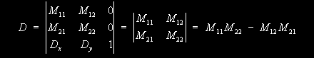
Although applications can use the DPtoLP function to obtain the world coordinates for a given set of physical coordinates, it is sometimes useful to explicitly obtain the transformation matrix corresponding to the inverse transform. In order to obtain the inverse matrix, one should first calculate the determinant of the transformation matrix:
If this value is zero, the inverse matrix does not exist. This happens when the world transformation is pathological, and maps many points in world space to the same point in page space, for example, when it maps world space onto a line in page space. In this case, a point in page space no longer corresponds to a unique point in world space and thus the inverse transformation is not possible.
Once the determinant has been obtained, the inverse matrix can be calculated easily:
Accordingly, here is a short function (Listing 11.1) that creates the inverse transform of a world transform. If the inverse transform does not exist, the function returns the identity transform. The function's return value is set to FALSE in this case to indicate an error. In keeping with the tradition of other XFORM-related functions, InvertTransform also accepts the same pointer for both the input and the output XFORM structure.
BOOL InvertTransform(LPXFORM lpxformResult, CONST XFORM *lpxform)

{

    XFORM xformTmp;

    FLOAT D;

    D = lpxform->eM11*lpxform->eM22 - lpxform->eM12*lpxform->eM21;

    if (D == 0.0)

    {

        lpxformResult->eM11 = 1.0;

        lpxformResult->eM12 = 0.0;

        lpxformResult->eM21 = 0.0;

        lpxformResult->eM22 = 1.0;

        lpxformResult->eDx = 0.0;

        lpxformResult->eDy = 0.0;

        return FALSE;

    }

    xformTmp.eM11 = lpxform->eM22 / D;

    xformTmp.eM12 = -lpxform->eM12 / D;

    xformTmp.eM21 = -lpxform->eM21 / D;

    xformTmp.eM22 = lpxform->eM11 / D;

    xformTmp.eDx = (lpxform->eM21*lpxform->eDy -

                    lpxform->eM22*lpxform->eDx) / D;

    xformTmp.eDy = (lpxform->eM12*lpxform->eDx -

                    lpxform->eM11*lpxform->eDy) / D;

    *lpxformResult = xformTmp;

    return TRUE;

}
On a final note, the SetWorldTransform function will fail unless the graphics mode for the device context has first been set to GM_ADVANCED using the SetGraphicsMode function. In order to reset the graphics mode to GM_COMPATIBLE, applications must first reset the world transformation matrix to the identity matrix.
Drawing Objects
Coordinate transformations define where a drawing is placed on the output device. What the drawing looks like is defined by the use of GDI objects.
GDI offers a variety of drawing objects: pens, brushes, fonts, palettes, and bitmaps. Applications that use such objects must perform the following steps:
- Create the GDI object.
- Select the GDI object into the device context.
- Call GDI output functions.
- Select the object out of the device context.
- Destroy the object.
GDI objects are created using any one of a variety of functions that we will acquaint ourselves with in a moment. Once created, a GDI object is referred to by a handle and can be selected into the device context using the SelectObject function. (Palettes are selected using SelectPalette.) This function also returns a handle to the previously selected pen, brush, font, or bitmap; when drawing is completed, this can be used to restore the device context to its previous state. Unused objects are destroyed using the DeleteObject function.
It is not always necessary to create a GDI object from scratch. Applications can also retrieve predefined system objects using the GetStockObject function. GetStockObject can be used to retrieve a handle to a variety of pens, brushes, fonts, and the system palette. While it is not necessary to call DeleteObject for a stock object, it is not harmful either.
Pens
Pens are used to draw lines, curves, and the contours of other shapes. A pen is created using the CreatePen function. When calling CreatePen, applications specify the pen's width, style, and color.
Pen color is specified as an RGB value; however, if there is matching entry in the logical palette, Windows usually substitutes the nearest palette color. The exception is the case when the width of the pen is greater than one and the style is PS_INSIDEFRAME; in this case, Windows uses a dithered color.
Dashed and dotted pen styles are not supported for pens with a width greater than one. However, in the case of Windows NT, such pens can be created using the ExtCreatePen function. This function is also available under Windows 95, but its utility is limited.
ExtCreatePen also gives greater control over the shapes of joins and end caps.
Another function that can be used to create a pen is the CreatePenIndirect function. This function takes a pointer to a LOGPEN structure as its parameter. The LOGPEN structure defines the pen's width, color, and style.
Drawing with a pen is affected by the foreground mix mode. This mode is set using the SetROP2 function. There are several settings that define various logical operations between the pen color and the pixel color. The current mixing mode can be retrieved using the GetROP2 function.
Brushes
Brushes are used to fill the interior of drawing shapes. The use of a brush defines the interior color and pattern.
A brush is created by a call to the CreateBrushIndirect function. This function accepts a pointer to a LOGBRUSH structure, which specifies the brush style, color, and pattern.
A brush pattern can be based on a bitmap. If the brush style is set to the values BS_DIBPATTERN or BS_DIBPATTERNPT, the lbStyle member of the LOGBRUSH structure specifies a handle to a bitmap.
Alternatively, a brush can be hatched; in this case, the lbStyle member of the LOGBRUSH structure specifies the hatch pattern.
The lbColor member specifies the foreground color of a hatched brush. However, the background color and mode are controlled by the SetBkColor and SetBkMode functions, respectively.
A specific problem related to pattern and hatch brushes is the problem of brush origin. In order to provide a smooth appearance, it is necessary to align the origin of a brush bitmap or hatch brush pattern when portions of a shape are drawn at different times. Under Windows 95, this is accomplished by calling UnrealizeObject every time before a brush is selected into a device context. This is not necessary under Windows NT, which tracks brush origins.
Applications can explicitly specify the brush origin through SetBrushOrgEx. The brush origin is a pair of coordinates that specify the displacement of the brush pattern relative to the upper-left corner of the window's client area.
There are several additional functions assisting in the creation and use of brushes. Solid brushes, pattern brushes, and hatch brushes can be created by calling CreateSolidBrush, CreatePatternBrush, and CreateHatchBrush, respectively. Brushes based on device-independent bitmaps can be created with CreateDIBPatternBrushPt.
Drawing the interior of an object is also affected by the foreground mix mode setting as specified by a call to the SetROP2 function.
Fonts
Before an application can output any text, it must select a logical font for text output. Logical fonts are created by calling the CreateFont function.
Users who are accustomed to applications that enable them to explicitly select a font by name, attributes, and size may find using CreateFont confusing at first. Although it is still possible to select a font by name, CreateFont offers a selection of a large number of additional parameters.
However, one has to realize that this method of creating a logical font is yet another feature through which Windows implements complete device-independence. Instead of making applications dependent on the presence of a specific font (which may not be available on all output devices, or may not be available on different computers) fonts are selected on the basis of their characteristics. When an application requests a font through CreateFont, Windows supplies, from the set of available fonts, the font that matches the requested characteristics best.
Nevertheless, it is possible to specify the name and size of a typeface to CreateFont. If this is done, Windows will attempt to select the desired font if it is available on the system.
Applications can also use CreateFontIndirect to obtain a logical font. This function takes a pointer to a LOGFONT structure as its parameter. This function is especially useful when used in conjunction with the Font Selection Common Dialog, which returns the user's choice in the form of a LOGFONT structure.
The EnumFontFamilies function can be used to enumerate all font families, or the fonts in a font family.
Many other font-related functions assist the application programmer. For example, functions such as GetCharABCWidths help determining the width of characters. The function GetTabbedExtent or GetTextExtentPoint32 calculate the width and height of a text string.
Applications can also install and remove fonts using the AddFontResource, CreateScalableFontResource, and RemoveFontResource functions.
Palettes
Palettes would not be necessary if all output devices were capable of displaying the full range of colors defined by a 24-bit RGB value. Unfortunately, most lower cost display devices offer a compromise between color depth and screen resolution. Most PCs nowadays operate using a screen resolution of 800x600, 1024x768, or 1280x1024 using 256 colors.
Whether a given device supports palettes can be determined by calling the GetDeviceCaps function and checking for the RC_PALETTE flag in the RASTERCAPS value. For these devices, a color palette defines the colors that are currently available for use by applications.
The system palette specifies all colors that can be currently displayed by the device. However, applications cannot directly modify the system palette, although they can view its contents through the GetSystemPaletteEntries function. The system palette contains a number (usually 2–20) of static colors that cannot be modified by palette changes. However, applications can set the number of static colors using the SetSystemPaletteUse function.
The default palette has typically 20 color entries, although this may vary from device to device. If an application requests a color that is not in the palette, Windows approximates the color by selecting the closest match from the palette or, in the case of solid brushes, by using dithering. However, this may not be sufficient for color-sensitive applications.
What applications can do is specify a logical palette to replace the default palette. A logical palette may contain several colors (up to the number of colors defined by the SIZEPALETTE value, returned by GetDeviceCaps). A logical palette is created by a call to CreatePalette, and its colors can later be modified by calling SetPaletteEntries. A palette is selected into a device context using the SelectPalette function. A palette that is no longer needed can be deleted by calling DeleteObject.
Before use, a palette needs to be realized using the RealizePalette function. In the case of the display device, depending on whether the palette is a foreground palette or a background palette, Windows realizes the palette differently. A palette can be selected as the foreground palette if the window for which it is selected is either the active window or a descendant of it. There can be only one foreground palette in the system at any given time. The critical difference is that a foreground palette can overwrite all nonstatic colors in the system palette. This is accomplished by marking all nonstatic entries unused before a foreground palette is realized.
When a palette is realized, Windows fills the unused entries in the system palette with entries from the logical palette. If there are no more unused entries, Windows maps the remaining colors in the logical palette using the closest matching color in the physical palette or using dithering. Windows always realizes the foreground palette first, followed by the remaining background palettes on a first come, first served basis.
It is important to realize that any changes to the system palette are global in nature; that is, they affect the entire display surface, not just the application's window. Changes in the system palette may cause applications to redraw their window contents. Because of this, there is an advantage to specifying a palette as a background palette; this avoids palette changes when the window for which the palette has been realized gains or loses focus.
Windows defines some palette-related messages. A top-level window receives a WM_PALETTECHANGED message when Windows changes the system palette. Before a top-level window becomes the active window, it receives a WM_QUERYNEWPALETTE message, enabling the application to realize its palette. The application can do this by calling SelectPalette, UnrealizeObject, and RealizePalette.
An interesting feature of palettes is palette animation. This technique uses periodic changes in the logical palette to create the impression of animation. Applications can use the AnimatePalette function for this purpose.
In order to ensure that a given color from a palette is selected (especially important when palette animation is concerned) applications should use the PALETTEINDEX or PALETTERGB macros.
An application that implements simple palette animation is shown in Listing 11.2. This application can be compiled from the command line by typing cl animate.cpp gdi32.lib user32.lib. Once again, note that this application only works when your video hardware is configured for a 256-color palette-enabled mode.
#include <windows.h>

struct

{

    WORD palVersion;

    WORD palNumEntries;

    PALETTEENTRY palPalEntry[12];

} palPalette =

{

    0x300,

    12,

    {

        {0xFF, 0x00, 0x00, PC_RESERVED},

        {0xC0, 0x40, 0x00, PC_RESERVED},

        {0x80, 0x80, 0x00, PC_RESERVED},

        {0x40, 0xC0, 0x00, PC_RESERVED},

        {0x00, 0xFF, 0x00, PC_RESERVED},

        {0x00, 0xC0, 0x40, PC_RESERVED},

        {0x00, 0x80, 0x80, PC_RESERVED},

        {0x00, 0x40, 0xC0, PC_RESERVED},

        {0x00, 0x00, 0xFF, PC_RESERVED},

        {0x40, 0x00, 0xC0, PC_RESERVED},

        {0x80, 0x00, 0x80, PC_RESERVED},

        {0xC0, 0x00, 0x40, PC_RESERVED}

    }

};

POINT pt12[12] =

{

    {0, 1000},

    {500, 866},

    {866, 500},

    {1000, 0},

    {866, -500},

    {500, -866},

    {0, -1000},

    {-500, -866},

    {-866, -500},

    {-1000, 0},

    {-866, 500},

    {-500, 866}

};

void Animate(HWND hwnd, HPALETTE hPalette)

{

    HDC hDC;

    PALETTEENTRY pe[12];

    HPALETTE hOldPal;

    static int nIndex;

    int i;

    for (i = 0; i < 12; i++)

        pe[i] = palPalette.palPalEntry[(i + nIndex) % 12];

    hDC = GetDC(hwnd);

    hOldPal = SelectPalette(hDC, hPalette, FALSE);

    RealizePalette(hDC);

    AnimatePalette(hPalette, 0, 12, pe);

    nIndex = (++nIndex) % 12;

    SelectPalette(hDC, hOldPal, FALSE);

    ReleaseDC(hwnd, hDC);

}

void DrawCircle(HWND hwnd, HPALETTE hPalette)

{

    HDC hDC;

    PAINTSTRUCT paintStruct;

    RECT rect;

    SIZE sizeO;

    POINT ptO;

    HPALETTE hOldPal;

    int i;

    hDC = BeginPaint(hwnd, &paintStruct);

    if (hDC != NULL)

    {

        hOldPal = SelectPalette(hDC, hPalette, FALSE);

        RealizePalette(hDC);

        GetClientRect(hwnd, &rect);

        DPtoLP(hDC, (LPPOINT)&rect, 2);

        ptO.x = (rect.left + rect.right) / 2;

        ptO.y = (rect.top + rect.bottom) / 2;

        sizeO.cx = MulDiv((rect.right - rect.left), 2, 3);

        sizeO.cy = MulDiv((rect.bottom - rect.top), 2, 3);

        for (i = 0; i < 12; i++)

        {

            HBRUSH hbr;

            HBRUSH hbrOld;

            hbr = CreateSolidBrush(PALETTEINDEX(i));

            hbrOld = (HBRUSH)SelectObject(hDC, hbr);

            Ellipse(hDC,

                ptO.x + MulDiv(sizeO.cx, pt12[i].x - 259, 2000),

                ptO.y + MulDiv(sizeO.cy, pt12[i].y - 259, 2000),

                ptO.x + MulDiv(sizeO.cx, pt12[i].x + 259, 2000),

                ptO.y + MulDiv(sizeO.cy, pt12[i].y + 259, 2000)

            );

            SelectObject(hDC, hbrOld);

            DeleteObject(hbr);

        }

        SelectPalette(hDC, hOldPal, FALSE);

        EndPaint(hwnd, &paintStruct);

    }

}

LRESULT CALLBACK WndProc(HWND hwnd, UINT uMsg,

                         WPARAM wParam, LPARAM lParam)

{

    static HPALETTE hPalette;

    switch(uMsg)

    {

        case WM_CREATE:

            hPalette = CreatePalette((LPLOGPALETTE)&palPalette);

            break;

        case WM_PAINT:

            DrawCircle(hwnd, hPalette);

            break;

        case WM_TIMER:

            Animate(hwnd, hPalette);

            break;

        case WM_DESTROY:

            DeleteObject(hPalette);

            hPalette = NULL;

            PostQuitMessage(0);

            break;

        default:

            return DefWindowProc(hwnd, uMsg, wParam, lParam);

    }

    return 0;

}

int WINAPI WinMain(HINSTANCE hInstance, HINSTANCE hPrevInstance,

                                        LPSTR d3, int nCmdShow)

{

    MSG msg;

    HWND hwnd;

    WNDCLASS wndClass;

    if (hPrevInstance == NULL)

    {

        memset(&wndClass, 0, sizeof(wndClass));

        wndClass.style = CS_HREDRAW | CS_VREDRAW;

        wndClass.lpfnWndProc = WndProc;

        wndClass.hInstance = hInstance;

        wndClass.hCursor = LoadCursor(NULL, IDC_ARROW);

        wndClass.hbrBackground = (HBRUSH)(COLOR_WINDOW + 1);

        wndClass.lpszClassName = "HELLO";

        if (!RegisterClass(&wndClass)) return FALSE;

    }

    hwnd = CreateWindow("HELLO", "HELLO",

                        WS_OVERLAPPEDWINDOW,

                        CW_USEDEFAULT, 0, CW_USEDEFAULT, 0,

                        NULL, NULL, hInstance, NULL);

    ShowWindow(hwnd, nCmdShow);

    UpdateWindow(hwnd);

    SetTimer(hwnd, 1, 200, NULL);

    while (GetMessage(&msg, NULL, 0, 0))

        DispatchMessage(&msg);

    KillTimer(hwnd, 1);

    return msg.wParam;

}
This application draws a series of twelve circles. Each circle has a different color, selected from a logical palette. The application also installs a timer; whenever a WM_TIMER message is received, it makes a call to the AnimatePalette function.
Bitmap Objects
Bitmaps are also treated as GDI objects. Typically, applications either draw into bitmaps, or transfer the contents of a bitmap to an output device.
What exactly is a bitmap? In terms of its visual appearance, it is a rectangular array of pixels. Each pixel can have a different color, represented in the form of one or more bits. The actual number of bits depends on the color depth of the bitmap. For example, a bitmap with a color depth of 8 bits can represent up to 256 colors; a true color bitmap can represent up to 16,777,216 colors using 24 bits per pixel.
A blank GDI bitmap object is created using the CreateBitmap function. Although suitable for creating color bitmaps, it is recommended that CreateBitmap be used for monochrome bitmaps only; for color bitmaps, use the CreateCompatibleBitmap function.
Bitmap objects are device dependent. Functions exist that enable applications to write into Device-Independent Bitmaps (DIBs). (This is what is stored in Windows BMP files.)
Applications can draw into a bitmap by selecting the bitmap into a memory device context.
To load a bitmap from a resource file, use the LoadBitmap function. This function creates a bitmap object and initializes it with the bitmap from the resource file, as specified by the function's second parameter.
Clipping
The technique of clipping is of fundamental importance in a multitasking windowing environment. Thanks to this technique, applications do not accidentally write to the display outside the client area of their windows, nor does it present a problem when parts of an application's window are covered or off-screen.
In addition to these uses of clipping by the system, applications are also given explicit access to many clipping functions. They can define a clipping region for a device context and limit graphical output to that region.
A clipping region is typically, but not always, a rectangular region. There are several types of regions and corresponding functions that can be used to create them, summarized in Table 11.1.
Symbolic Identifier |
Description |
|
Elliptical Region |
CreateEllipticRgn, CreateEllipticRgnIndirect |
|
Polygonal Region |
CreatePolygonRgn, CreatePolyPolygonRgn |
|
Rectangular Region |
CreateRectRgn, CreateRectRgnIndirect |
|
Rounded Rectangular Region |
CreateRoundRectRgn |
Applications can select a clipping region into a device context by calling SelectObject or SelectClipRgn. The effects of these two functions are equivalent. Another function that enables combining a new region with the existing clipping region in the fashion of the CombineRgn function is SelectClipRgnExt.
Another form of clipping is accomplished by the use of clip paths. Clip paths can define complex clipping shapes that could not be defined through clipping regions. A clipping path is a path created through the use of the BeginPath and EndPath functions, and then selected as the clipping path by calling SelectClipPath.
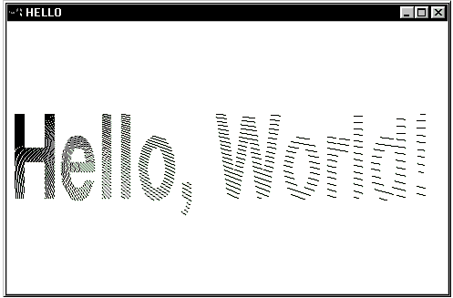
Clip paths can be used to produce interesting special effects. One example is demonstrated in Listing 11.3. This application, shown in Figure 11.9, uses a text string to create a clip path. You can compile this program by typing cl clippath.c gdi32.lib user32.lib at the command line.
Figure 11.9. Using clip paths.
#include <windows.h>

#include <math.h>

void DrawHello(HWND hwnd)

{

    PAINTSTRUCT paintStruct;

    RECT rect;

    HFONT hFont;

    SIZE sizeText;

    POINT ptText;

    HDC hDC;

    double a, d, r;

    hDC = BeginPaint(hwnd, &paintStruct);

    if (hDC != NULL)

    {

        GetClientRect(hwnd, &rect);

        DPtoLP(hDC, (LPPOINT)&rect, 2);

        hFont = CreateFont((rect.bottom - rect.top) / 2,

                           (rect.right - rect.left) / 13, 0, 0,

                           FW_HEAVY, FALSE, FALSE, FALSE,

                           ANSI_CHARSET, OUT_DEFAULT_PRECIS,

                           CLIP_DEFAULT_PRECIS, DEFAULT_QUALITY,

                           DEFAULT_PITCH | FF_DONTCARE, "Arial");

        SelectObject(hDC, hFont);

        GetTextExtentPoint32(hDC, "Hello, World!", 13, &sizeText);

        ptText.x = (rect.left + rect.right - sizeText.cx) / 2;

        ptText.y = (rect.top + rect.bottom - sizeText.cy) / 2;

        SetBkMode(hDC, TRANSPARENT);

        BeginPath(hDC);

        TextOut(hDC, ptText.x, ptText.y, "Hello, World!", 13);

        EndPath(hDC);

        SelectClipPath(hDC, RGN_COPY);

        d = sqrt((double)sizeText.cx * sizeText.cx +

                         sizeText.cy * sizeText.cy);

        for (r = 0; r <= 90; r+= 1)

        {

            a = r / 180 * 3.14159265359;

            MoveToEx(hDC, ptText.x, ptText.y, NULL);

            LineTo(hDC, ptText.x + (int)(d * cos(a)),

                        ptText.y + (int)(d * sin(a)));

        }

        EndPaint(hwnd, &paintStruct);

    }

}

LRESULT CALLBACK WndProc(HWND hwnd, UINT uMsg,

                         WPARAM wParam, LPARAM lParam)

{

    switch(uMsg)

    {

        case WM_PAINT:

            DrawHello(hwnd);

            break;

        case WM_DESTROY:

            PostQuitMessage(0);

            break;

        default:

            return DefWindowProc(hwnd, uMsg, wParam, lParam);

    }

    return 0;

}

int WINAPI WinMain(HINSTANCE hInstance, HINSTANCE hPrevInstance,

                                        LPSTR d3, int nCmdShow)

{

    MSG msg;

    HWND hwnd;

    WNDCLASS wndClass;

    if (hPrevInstance == NULL)

    {

        memset(&wndClass, 0, sizeof(wndClass));

        wndClass.style = CS_HREDRAW | CS_VREDRAW;

        wndClass.lpfnWndProc = WndProc;

        wndClass.hInstance = hInstance;

        wndClass.hCursor = LoadCursor(NULL, IDC_ARROW);

        wndClass.hbrBackground = (HBRUSH)(COLOR_WINDOW + 1);

        wndClass.lpszClassName = "HELLO";

        if (!RegisterClass(&wndClass)) return FALSE;

    }

    hwnd = CreateWindow("HELLO", "HELLO",

                        WS_OVERLAPPEDWINDOW,

                        CW_USEDEFAULT, 0, CW_USEDEFAULT, 0,

                        NULL, NULL, hInstance, NULL);

    ShowWindow(hwnd, nCmdShow);

    UpdateWindow(hwnd);

    while (GetMessage(&msg, NULL, 0, 0))

        DispatchMessage(&msg);

    return msg.wParam;

}
This application draws the text "Hello, World!" using a large Arial font—the actual size is calculated based on the size of the client area. This text forms the clipping path. Next, a series of lines is drawn from the upper-left corner of the text rectangle; due to clipping, only the portions that fall within characters are seen.
Drawing Functions
We have reviewed the idea of a device context as the "canvas" onto which GDI functions paint graphic output; we have reviewed the tools GDI performs the painting with, such as pens, brushes, or fonts. What is left is a review of the actual drawing operations used by the GDI.
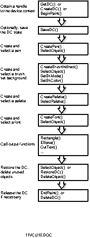
The typical steps taken by an application are illustrated in Figure 11.10. They include obtaining a handle to the device context, setting up the device context for drawing, performing drawing operations, restoring the previous state of the device context, and finally, releasing the device context. Naturally, specific applications may elect to perform these steps in a different order, leave out irrelevant steps, or invoke other initialization or drawing functions to satisfy specific requirements.
Figure 11.10. Typical steps of GDI output.
Lines
The simplest drawing function in Windows creates a line. A simple line is created by a call to the MoveToEx function, followed by a call to the LineTo function. The MoveToEx function updates the current position, which is a point in the coordinate space of the device context that is used by many drawing functions. The LineTo function creates a line from that position to the position specified through its parameters. The line is drawn using the pen that is currently selected into the device context.
In the case of raster devices, a line is generally drawn using a DDA (Digital Differential Analyzer) algorithm. This algorithm determines which pixels in the drawing surface should be highlighted. Specialized applications that require the use of a nonstandard DDA algorithm can use the LineDDA function.
A polyline is a line consisting of several line segments. A polyline is defined by an array of points, a pointer to which is passed to the Polyline function. Polyline does not use or update the current position; in contrast, PolylineTo begins drawing from the current position, and updates the current position to reflect the last point in the polyline.
The PolyPolyline function can be used to draw a series of polylines using a single function call.
Curves
The simplest function to draw a curve is the Arc function. A curve drawn by this function is actually a segment of an ellipse. The arc is drawn using the current pen. The ArcTo function is identical to the Arc function, except that it also updates the current position.
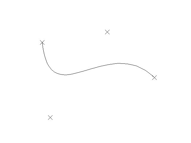
Win32 applications can also draw Bázier curves. Bázier curves represent a cubic interpolation between two endpoints, as defined by two control points. An example for a Bázier curve is shown in Figure 11.11.
The PolyBezier function draws one or more Bázier curves. One of its parameters is a pointer to an array of points used to define these curves. The endpoint of one curve serves as the starting point of the next curve; consequently, the number of points in this array must be a multiple of three plus one (the first starting point), that is, 4, 7, 10, and so on.
The PolyBezierTo function is identical to the PolyBezier function except that it also updates the current position.
Win32 also provides for combinations of lines and curves. The outline of a pie chart can be drawn using the AngleArc function. More complex combinations of lines and curves can be created using the PolyDraw function.
Filled Shapes
In addition to lines and curves, GDI drawing functions can also be used to create filled shapes. The outline of filled shapes, similar to lines and curves, is drawn using the current pen. The interior of shapes is painted using the current brush.
Perhaps the simplest GDI shape is a rectangle. A rectangle is created by calling the Rectangle function. Variants of the Rectangle function include RoundRect (draws a rectangle with rounded corners), FillRect (draws the interior of a rectangle using a specific brush), FrameRect (draws the frame of a rectangle using a specific brush), and InvertRect (inverts a rectangular area on the screen).
Other shapes can be created using the following functions: Ellipse, Chord, Pie, Polygon. A series of polygons can be drawn using the single function call PolyPolygon.
Regions
I have already mentioned regions and their role in clipping. However, the GDI offers several other uses for regions.
Regions (summarized in Table 11.1) can be filled (FillRgn, PaintRgn), framed (FrameRgn) or inverted (InvertRgn).
Regions can be combined using the CombineRgn function. To test whether two regions are identical, use the EqualRgn function. A region can be displaced by a specified offset using OffsetRgn.
The bounding rectangle of a region can be obtained by calling GetRgnBox. To determine whether a specific point or a rectangle fall within the region, call PtInRegion or RectInRegion, respectively.
Bitmaps
We have already talked about bitmap objects. Windows offers a variety of functions through which these objects can be copied and manipulated.
Individual pixels in a bitmap can be set using the SetPixel function. The GetPixel function retrieves the color of the specified pixel.
A region in a bitmap bounded by pixels of specific colors can be filled using the ExtFloodFill function.
Perhaps the simplest of functions that manipulate whole bitmaps is the BitBlt function. This function copies a bitmap from one device context to another. It is often used to copy portions of a bitmap in a memory device context to the screen or vice versa; however, it can also be used to copy a bitmap to a different location within the same device context.
BitBlt returns an error if the source and destination device contexts are not compatible. To ensure that a memory device context is compatible with the display, use the CreateCompatibleDC function to create the device context.
Although BitBlt uses logical coordinates and performs the necessary scaling when copying bitmaps, it fails if a rotation or shear transformation is in effect.
In addition to copying source pixels to the destination, BitBlt can also combine source and destination pixels using a variety of pixel operations.
A variant of the BitBlt function is MaskBlt. This function uses a third bitmap as a mask when performing the operation.
The PatBlt function paints the destination bitmap using the currently selected brush.
The StretchBlt function copies the source bitmap to the destination bitmap, stretching or compressing the bitmap as necessary to fit it into the destination rectangle. The stretching can be controlled by the SetStretchBltMode function.
The PlgBlt function copies the source bitmap into a destination parallelogram. The parallelogram is defined by an array of three points representing three of its vertices; the fourth vertex is calculated using the vector equation D = B + C - A.
The bitmaps discussed so far are associated by a specific device context; hence, they are device-dependent. Windows also handles device-independent bitmaps, which are stored in memory or on disk. A DIB is specified through a BITMAPINFO structure. Applications can create a DIB using the CreateDIBitmap function. The bits in a DIB can be set using SetDIBits; the DIB's color table can be modified using SetDIBColorTable. The SetDIBitsToDevice function copies a DIB to a device; the StretchDIBits function can be used to copy bits from a device to a device-independent bitmap.
Paths
We have already encountered paths in the context of clipping. Paths represent complex shapes created by a series of calls to many GDI output functions, including, for example, the Rectangle, Ellipse, TextOut, LineTo, PolyBezier, Polygon functions.
A path is created by calling the BeginPath function, performing the drawing operations that form part of the path, and calling EndPath. The pair of calls to BeginPath and EndPath is often referred to as a path bracket.
Calling EndPath selects the path into the device context. Applications can then do any of the following:
- Draw the outline or interior of the path, or both (StrokePath, FillPath, StrokeAndFillPath)
- Use the path for clipping (SelectClipPath)
- Convert the path into a region (PathToRegion)
- Modify the path (GetPath, FlattenPath, WidenPath)
Text Output
The simplest GDI text output function is the TextOut function. This function outputs text at the specified coordinates using the currently selected font. The TabbedTextOut function is a variant of TextOut that also expands tab characters. The PolyTextOut function can be used to output a series of text strings using a single function call. The ExtTextOut function also accepts a rectangle that can be used for opaquing or clipping.
The DrawText and DrawTextEx functions can be used to output text with special formatting in a specific rectangle.
Text output is affected by formatting attributes, which are set through the SetTextColor, SetTextAlign, SetBkColor, SetBkMode, SetTextCharacterExtra, and SetTextJustification functions.
Applications can obtain the size of a block of text before drawing it by calling GetTabbedTextExtent or GetTextExtentPoint32.
Notes About Printing
The GDI is also responsible for providing hardcopy output on printers, plotters, and outer output devices. In the case of most applications, knowing the details of the printing process is not necessary; creating output to a hardcopy device is no different from creating output to the display, using the standard set of GDI function calls on a printer device context. While sometimes it is necessary to be aware of the physical characteristics of the output page and the limitations of the device (for example, a plotter may not support bitmap operations), WYSIWYG applications can most often reuse, with minimal modifications, the same code for printing that they use for display output.
There are several Windows components involved in printing. The primary component is the print spooler, which manages the printing process. The print processor converts spooled print jobs into calls to the device driver. The device driver generates raw output, which is then processed by the printer device. Finally, the port monitor passes raw device commands to the physical device through a specific port or network connection.
There are several Win32 functions for spooling print jobs, retrieving information about jobs and printers, and control the printing process.
Windows 3.1 applications often used printer escapes to carry out specific tasks. These have been superseded by new Win32 functions. New applications should not use the Escape function to control a printer.
Summary
The Windows GDI provides a device-independent set of functions that applications can use to create graphic output on all Windows-compatible output devices. The GDI is used to create output on the display screen, on printers, plotters, FAX modems, and other specialized graphic devices.
All graphic output is directed to device contexts. A device context provides a description of the output device, its characteristics and parameters, and also acts as an interface between the device-independent GDI routines and the device driver software. In a manner of speaking, the device context is the "canvas" on which GDI drawing operations are performed.
GDI uses a collection of tools for graphic output:
- Pens are used to draw lines or the contours of shapes.
- Brushes are used to fill the interior of shapes.
- Fonts are used for text output.
- Bitmaps are rectangular arrays of pixels that can be drawn to using memory device contexts and manipulated or transferred between device contexts using bitmap manipulation functions.
- Palettes are logical collections of colors that the GDI matches as closely as possible by configuring the color settings of the display device.
- Regions are regular or irregular shapes that can be used, for example, to define clipping.
Clipping is one of the key capabilities on the GDI. Thanks to clipping, applications do not need to confine their output to the visible part of their windows. Applications can also use clipping operations explicitly to create various graphical effects.
The coordinate mapping, drawing tools, and clipping define how the GDI performs its drawing operations. What is actually drawn is specified by a series of graphic functions. Applications can draw lines, curves, and filled shapes; can output text; and can manipulate bitmaps. Applications can also utilize paths for a variety of purposes.
The GDI provides a series of extra functions to facilitate greater control over printing and spooling to the printer. However, unless an application needs to explicitly control the printing process, it is rarely necessary to use these capabilities. Furthermore, in the case of most WYSIWYG applications, it is possible to reuse display output code for printing with minimal modifications.
Popular Tutorials
-
 MS Access
1109
MS Access
1109
-
 C++
1222
C++
1222
-
 HTML
584
HTML
584
-
 JavaScript
616
JavaScript
616
-
 Vbscript
873
Vbscript
873
-
 Oracle
473
Oracle
473
-
 VC++
875
VC++
875
-
 SQL
2959
SQL
2959
-
 XML
514
XML
514
-
 Java
814
Java
814
-
 Perl
455
Perl
455
-
 Linux
451
Linux
451

